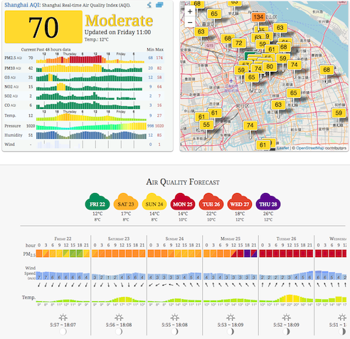
I live and work in Shanghai. We talk about the Air Quality Index (AQI) like people in other places talk about the weather (incidentally, we talk about the weather as well). Die-hard enthusiasts can get an air quality forecast:
I’ve been looking for something to justify the existance of my Raspberry Pi, and came across this project on HackerNoon (and a very recent update) using an SDS011 particle sensor to measure AQI. Fun Fact: the picture at the top of the HackerNoon post is Shanghai, West of the HuangPu River (“Puxi”)- most photos are of the Eastern skyline (“Pudong”).
There’s several existing projects:
- zefanja/aqi (Python; by the author of the above posts)
- rust-nova-sds011 (Rust)
- sds011_particle_sensor (Python) and “sds011-rs” (Rust) it inspired
- Probably many more…
We’ll primarily focus on the last two along with serial-rs which both Rust versions used.
PC
It’s easiest to initially get started on PC/Mac using the USB adapter that comes with the sensor.
“sds011-rs” provides a direct link to the Mac driver for the USB adapter (“ch341-uart converter”) and below that is support for Windows, etc. Follow the instructions in the ReadMe.pdf inside the archive.
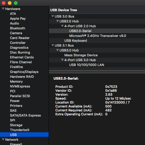
If you check “System Report” or “System Information” the adapter will come up as USB 2.0-Serial:
Find the name of the device:
$ ls /dev/tty.wch*

/dev/tty.wchusbserial141230
The number at the end seems to come from “Location ID” and may vary slightly if you re-connect the USB adapter.
Implementation
First we need to open the /dev/tty.wchusbserial141230 serial device:
pub fn new(path: &Path) -> Result<Self, serial::Error> {
    let serial_port = serial::open(path)?;
    let sensor = Sensor {
        serial_port,
        device_id: None,
    };
    Ok(sensor)
}

pub fn configure(&mut self, timeout: Duration) -> serial::Result<()> {
    const PORT_SETTINGS: serial::PortSettings = serial::PortSettings {
        baud_rate: serial::Baud9600,
        char_size: serial::Bits8,
        parity: serial::ParityNone,
        stop_bits: serial::Stop1,
        flow_control: serial::FlowNone,
    };

    self.serial_port.configure(&PORT_SETTINGS)?;
    self.serial_port.set_timeout(timeout)?;
    Ok(())
}
Before requesting a reading, make sure the sensor isn’t sleeping by setting it to the Measuring “work state”:
let wake_command = SendData::set_work_state(WorkState::Measuring);
sensor.send(&wake_command).unwrap();
Commands are 19 bytes long with the following format:
| 0 | 1 | 2 | 3 - 14 | 15 | 16 | 17 | 18 |
|---|---|---|---|---|---|---|---|
0xAA |
0xB4 |
Command | Data (trailing 0’s) | 0xFF |
0xFF |
Checksum | 0xAB |
“Command” field is one of the following:
#[repr(u8)]
#[derive(Debug, PartialEq, Clone, Copy)]
pub enum Command {
    /// Get/set reporting mode.  `Initiative` (0) to automatically generate measurements, or `Passive` (1) to use `Request` commands.
    ReportMode = 2,
    /// Query measurement.  When `ReportMode` is `Passive`
    Request = 4,
    /// Get device id
    DeviceId = 5,
    /// Get/set sleeping (0) or awake/measuring (1) state
    WorkState = 6,
    /// Get firmware version
    Firmware = 7,
    /// Get/set duty cycle
    DutyCycle = 8,
}
Format of “data” depends on the command:
| Bits | 3 | 4 - 14 | Details |
|---|---|---|---|
0 |
all 0 |
“Get” value (includes Request) |
| Bits | 3 | 4 - 14 | Details |
|---|---|---|---|
1 |
value (trailing 0s) |
“Set” value (excludes Request) |
The checksum is calculated by adding bytes 2 to 14 (from the command to before the checksum):
pub fn generate_checksum(data: &[u8]) -> u8 {
    let mut checksum: u8 = 0;
    for data in &data[2..] {
        checksum = checksum.wrapping_add(*data);
    }
    checksum
}

// Alternatively, using `u16` to prevent overflow and truncating/taking modulus
pub fn generate_checksum(data: &[u8]) -> u8 {
    let mut checksum: u16 = 0;
    for data in &data[2..] {
        checksum += u16::from(*data);
    }
    checksum as u8
}
Either using wrapping arithmetic, truncating, or using modulus (%- as seen in several implementations) to deal with overflow.
Note that in one of the implementations there’s checksum - 2. The - 2 is from the command terminating bytes 0xFF which is the two’s complement form of -1 (i.e. checksum + 0xFF + 0xFF is checksum - 1 - 1).
After sending a command, there is a response of 10 bytes:
| 0 | 1 | 2 - 5 | 6 - 7 | 8 | 9 | Details |
|---|---|---|---|---|---|---|
0xAA |
0xC0 |
Data | Device Id | Checksum | 0xAB |
Receive measurement with Initiative reporting or via Request with Passive reporting |
| 0 | 1 | 2 | 3 | 4 - 5 | 6 - 7 | 8 | 9 | Details |
|---|---|---|---|---|---|---|---|---|
0xAA |
0xC5 |
Command | 0 |
Value | Device Id | Checksum | 0xAB |
“Get” command |
0xAA |
0xC5 |
Command | 1 |
Value | Device Id | Checksum | 0xAB |
“Set” command |
Which can be read with code similar to (simplified for clarity):
type Response = [u8; 10];

let mut bytes_received = Response::default();
let mut num_bytes_received;
loop {
    // Read the first byte looking for a "Start" (0xAA)
    num_bytes_received = match self.serial_port.read(&mut bytes_received[..1]) {
        Ok(num_bytes) => num_bytes
        Err(_) => // Error handling
    };
    if num_bytes_received == 0 {
        //return
    }
    match Serial::try_from(bytes_received[0]) {
        Ok(Serial::Start) => {} // Ok, got `0xAA`
        other => continue;
    }

    // Read the second byte looking for either `0xC0` or `0xC5`
    num_bytes_received += match self.serial_port.read(&mut bytes_received[1..2]) {
        Ok(read) => read,
        Err(_) => // Error handling
    };
    let serial_read = Serial::try_from(bytes_received[1]);
    if serial_read == Ok(Serial::ResponseByte) || serial_read == Ok(Serial::ReceiveByte) {
        // Read remaining 8 bytes
        let num_bytes = self.serial_port.read(&mut bytes_received[2..])?;
        num_bytes_received += num_bytes;
        break;
    }
}
// Return all 10 bytes
bytes_received
Finally, the pm 2.5 and 10 readings can be calculated from the 10 byte response:
fn response_to_measurement(data: Response) -> SensorMeasurement {
    let pm2_5 = (f32::from(data[2]) + f32::from(data[3]) * 256.0) / 10.0;
    let pm10 = (f32::from(data[4]) + f32::from(data[5]) * 256.0) / 10.0;
    SensorMeasurement { pm2_5, pm10 }
}
Pi
We’ll assume you already have Raspbian installed and running on a Raspberry Pi 3 (although this likely also works for a 2).
Plug the SDS011 into a USB port and check the output of dmesg:
[69000.284345] usb 1-1.5: new full-speed USB device number 6 using dwc_otg
[69000.417442] usb 1-1.5: New USB device found, idVendor=1a86, idProduct=7523, bcdDevice= 2.63
[69000.417458] usb 1-1.5: New USB device strings: Mfr=0, Product=2, SerialNumber=0
[69000.417467] usb 1-1.5: Product: USB2.0-Serial
[69000.418425] ch341 1-1.5:1.0: ch341-uart converter detected
[69000.421856] usb 1-1.5: ch341-uart converter now attached to ttyUSB0
A device with the correct Vendor/Product ID is now attached to ttyUSB0, so the sensor is available as /dev/ttyUSB0.
You can copy the code over and build directly on the Pi. But, I’m impatient, so we’re going to cross-compile for armv7 using musl.
In .cargo/config (or ~/.cargo/config):
[target.armv7-unknown-linux-musleabihf]
linker = "arm-linux-musleabihf-gcc"
On the PC/Mac:
# 1. Build it
CROSS_COMPILE=arm-linux-musleabihf- cargo build --target armv7-unknown-linux-musleabihf
# 2. Copy it to the Pi (if `raspberrypi.local` doesn't work, use the pi's IP address)
scp target/armv7-unknown-linux-musleabihf/debug/pm25 pi@raspberrypi.local:~/
# 3. Ssh in and run it
ssh pi@raspberrypi.local ./pm25 /dev/ttyUSB0
It didn’t immediately work. Turns out the serial port timeout enabled with serial::unix::TTYPort::set_timeout() isn’t working. Rather than attempting a read and see if there’s a timeout to set the sensor to Measuring, just set it.
GPIO
The Pi 2/3 have plenty of USB ports, but depending on your usage it might be worth connecting the SDS011 to the GPIO pins rather than having the USB adapter sticking out.
The SDS011 pins are labeled clearly on both the sensor and the USB adapter and align with that found on the various Pis. You can confirm this by looking at a diagram of the Pi GPIO pins, starting with the upper-left corner of the board:
| Device | |||||
|---|---|---|---|---|---|
| SDS011 | NC | 5v | G | Rx | Tx |
| Pi3 | 5v | 5v | G | Tx (14) | Rx (15) |
So, the sensor can be connected directly to the Pi, like this:
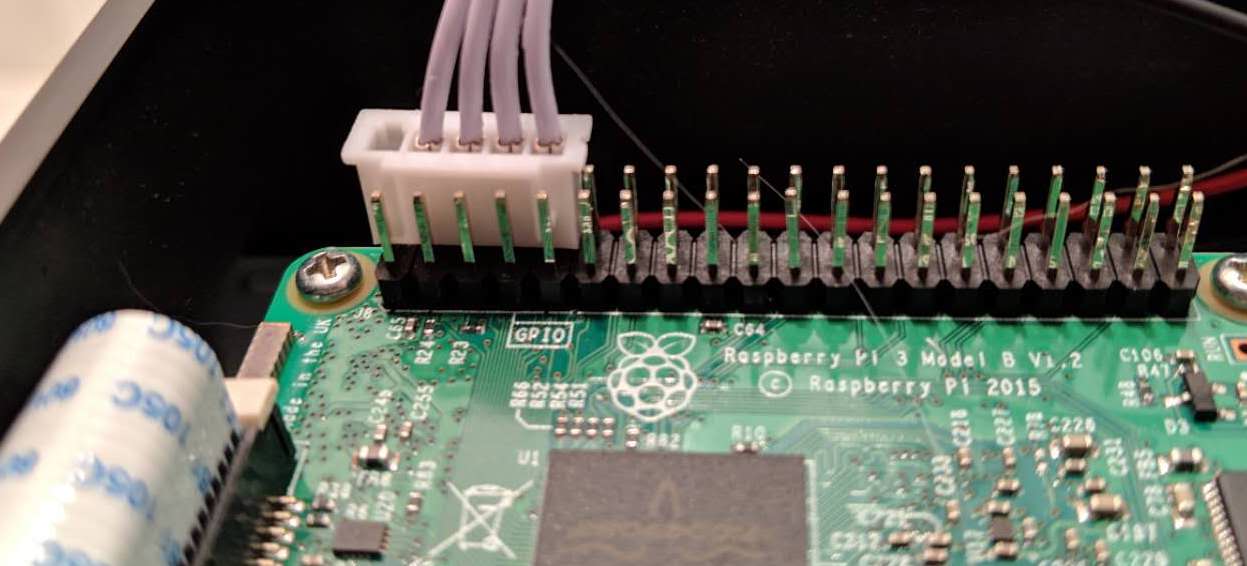
Make sure the wires connect the Pi and the SDS011 according to the above table (with Tx->Rx).
The official UART document is a bit unclear, but to use the serial GPIO (pins 14 and 15) the UART(s) on the Pi must be configured:
sudo echo "enable_uart=1" >> /boot/config.txt

sudo vim /boot/cmdline.txt
# Remove `console=serial0,115200`

# Restart for changes to take effect
sudo shutdown -r now
Now the sensor can be accessed via /dev/ttyS0.
Once again, things didn’t immediately work. Now serial::unix::TTYPort::read() only returns one byte at a time. Either need to replace it with read_exact() or use a loop:
while num_bytes_received < bytes_received.len() {
    let num_bytes = self.serial_port.read(&mut bytes_received[num_bytes_received..])?;
    num_bytes_received += num_bytes;
}
In Closing
Was a fun and pretty simple project. Some of my friends had a good laugh when I gave them live, “play-by-play” AQI readings during brunch on Saturday.
Pushed all the code to github.