Some areas of my apartment lack convenient outlets to power smart home devices. Running cables everywhere will decimate the fengshui of my abode, but living in a sunny climate makes solar power a palatable option. I ended up trying the “adafruit build” (see projects 1, 2, 3)- so named because all components are available from Adafruit:
- 6V 6W solar panel
- 3.7V 6600mAh Li-Ion battery
- USB/DC/Solar Li-Ion/Poly charger: charges battery via solar panel
- PowerBoost 500 converter: converts 3.7V from charger/battery to ~5V for USB-powered devices (like Raspberry Pi 3/4/Zero)
Given that the Raspberry Pi Zero consumes around 0.5W, a 6W solar panel and 6600mAh battery is overkill for many devices. Over-speccing now means:
- Don’t need to optimize software for power consumption during development (e.g. putting CPU or wifi to sleep)
- Can repurpose with more demanding devices
Some Assembly Required
The small number of components really only fit together one way and some basic soldering is required. Adafruit has a tutorial or you can follow one of the related projects mentioned above, but the instructions boil down to:
- Solder:
- Capacitor to solar charger (stripe is negative lead)
- USB-A connector to PowerBoost
- Connect:
- Solar panel to charger (via 1.3mm to 2.1mm DC jack adapter)
- Battery to charger’s
BATTconnector - PowerBoost converter to charger’s
LOADconnector (via spliced JST PH 2-pin cables)
And voila:
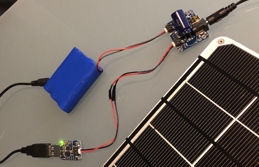
I didn’t have any shrink wrap on-hand so I used a snip of electrical tape for exposed wire bits.
Assuming everything is done correctly, expose the solar panel to sunlight, the red PWD and orange CHRG LEDs on the solar charger and the green PWR LED on the converter should be lit.
Details about the charger LEDs (from adafruit tutorial, figure 4-1 and table 5-1 from the datasheet):
| State | CHRG (“STAT1”) |
DONE (“STAT2”) |
PWR (“PG”) |
|---|---|---|---|
| Off | Off | Off | Off |
| Charging | On | Off | On |
| Charge Done | Off | On | On |
| Temp/Timer fault | On | On | On |
| Low battery output (3.1V) | On | Off | Off |
| No battery | Off | Off | On |
According to the forums (post #1 and #2), the red PWR LED will blink when there isn’t enough power coming from the solar panel. The large capacitor is used until the minimum charge voltage is reached then discharge into the battery; less light -> longer capacitor cycle -> slower blinking.
Details about the converter LEDs (from PowerBoost tutorial):
| State | LED |
|---|---|
| 5V output | green LED lit |
| Input below 3.2V | red PWR LED lit |
A Long Straw
Should you need to reach further away to drink up the solar rays:
- Switch the solar panel to 5.5/2.1mm via either:
- Use appropriate length of amply available, inexpensive 5.5/2.1mm DC extension cables (example)
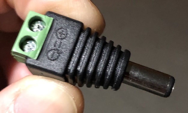
In my case, the solar panel’s 0.26m of cable was enough to place it outside the bathroom window, and an additional 1m allowed me to place the remaining electronics on the nearest shelf.
Winning
This was a fun and incredibly rewarding project.
On occasion I share these side projects with my family, but this was the first that garnered a reaction and aroused interest. Few people can appreciate the subtle nuances of software development, but in this foul Year of our Lord, 2019, everyone can grok the covetousness of portable USB power!
The modular nature of it also deserves attention. You should be able to disconnect the JST from the PowerBoost converter and hook the 3.7V from the charger/battery directly up to 3.3V devices. Plan to use an ultra-low-power Arduino? Swap out the 6W solar panel and 6600mAh battery for something more modest. Device needs 1-2A? Swap the PowerBoost 500 for a PowerBoost 1000.
It’s tempting to revisit my air-quality monitor, but no longer living in Shanghai I have little use for it.
Alternatives
There’s numerous other potential solutions if you’ve got different requirements (or hold a grudge against Adafruit). A by no means exhaustive list in no particular order:
- Projects:
- All-in-one Solutions:
- PiJuice: 1, 2
- Solar Pi Platter
- Witty Pi 2
- PiSolMan